Metro-MPI++: Accelerating Verilog/System Verilog Simulations
A GSoC project to automatically partition and parallelize hardware simulations in Verilator using MPI.

Project Description
As modern SoC designs get more and more complex, especially manycore-based ones, simulation performance becomes a serious bottleneck. RTL simulation is still the most accurate way to verify digital designs, but the traditional monolithic simulators don’t scale well when the design has many replicated hardware blocks like cores or NoC components. This often results in extremely long simulation times, which slows down the development design cycle.
Newer simulators do give us the option to do parallel simulation, but they lack one important aspect: they fail to give the simulator (or the compiler that does the parsing and AST construction) a perspective of the physical structure of the hardware design. Because of this, the preprocessing, AST construction, elaboration, and optimization follow a standard approach that a general-purpose software language compiler like GCC follows. However, unlike C and C++, HDLs carry much more information that is not visible to general-purpose compilers. An intuitive example would be the case of gem5: when we are modifying some structures like the O3 CPU model, it may happen that we are able to complete the building process of the binary without throwing any errors but later fail during the simulation. This happens because of the same reason—GCC does not know what this code represents, and it does exactly the same thing it does with other C++ code. Apart from this, the current parallel simulation frameworks lack the ability to scale.
To handle the scaling issue, my mentors, Dr. Guillem and Prof. Jonathan, have come up with a novel way of parallelizing RTL simulations, targeting OpenPiton, Metro-MPI. This novel approach breaks the entire binary simulating the whole design into smaller ones simulating a top-level system and partitioned/duplicated hardware blocks, keeping the hardware boundaries in consideration so that the data movement between these different binaries can be minimized. Then, these binaries are simulated in parallel on different threads across multiple nodes using MPI (Message Passing Interface), which is a de facto standard for communication among processes that model a parallel program running on a distributed memory system.
The reason we opted for this approach even though Verilator, an open-source SystemVerilog simulator, does provide an inbuilt partitioning and scheduling mechanism based on a 1989 paper “Partitioning and Scheduling Parallel Programs for Multiprocessors” is because this approach is too generic, and we can do better by making the partitioner and scheduler aware of the hardware structures.
In this project, Metro-MPI++, my goal was to take the same philosophy as in Metro-MPI and automatically enable it inside Verilator:
- To automatically detect the possible partitions that can be simulated in parallel.
- To extract as much information as possible about the connecting interface of these partitions to enable Verilator to make informed decisions.
- Generate intermediate files and structures needed to insert MPI to do parallel simulations.
Metro-MPI++ Workflow

To implement this idea in Verilator, first, we need to understand how exactly these RTL simulators work and what steps are involved from start to end. After a careful study, the most optimal place to implement this is just after the AST construction is completed, as we can get all the information about the entire design from all modules from the AST itself and before the elaboration step. As a result, the first approach we tried was to analyze the XML file that Verilator outputs, which contains information about the entire design. We found that it was sufficient to carry out our work since this XML file was generated from the AST.
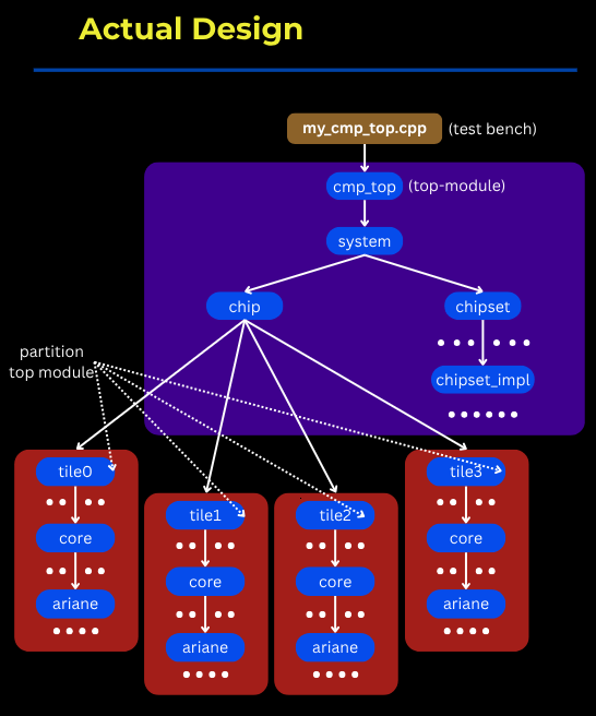
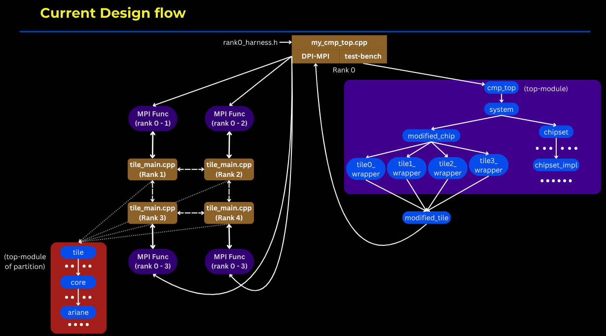
For further explanation of the same, let’s take the example of OpenPiton 2x2 configuration:
- First, we will do the analysis and find the possible top module of a partition.
- Second, we will find the ports that are involved in communication between partitions and with the system. Once found, we will also determine if they are active.
- Third, we plan to do the verilation of the detected partition separately with a test bench having MPI functions compatible with communicating with other partitions and the system.
- Fourth, we will generate the modified Verilog files that will replace the old ones to introduce the DPI functions and the static rank identifier.
- Fifth, we will verilate the rank 0, the system design, separately with the test bench same as earlier with minor modifications.
- Lastly, we will simulate the binaries in the classic MPI-style execution.
Prerequisite: Upgrading Verilator’s support in OpenPiton from v4 to v5
Before implementing the main partitioning and MPI integration features, the first critical step was to upgrade OpenPiton’s(the world’s first open-source, general-purpose, multithreaded manycore processor with a 64-bit Ariane RISC-V core) support for Verilator v5 from v4. The original framework relied on Verilator v4.x, but newer versions like v5.038 are already available; upgrading was essential for long-term maintainability and compatibility.
This upgrade introduced several challenges due to major internal changes in Verilator between v4.x and v5.x:
-
Common Issues in All Versions of Verilator v5.x:
- Precompiled Headers (pch): In Verilator v5.x, precompiled headers are used, whereas v4.x doesn’t rely on them. During the build, to avoid errors from directly invoking PCH files, I modified
verilator/include/verilated.mkto include the-cflag. This ensures that the compiler only generates object files without attempting to link at this stage. By doing so, the PCH files are compiled in advance, and when they are later referenced in the build process, they are already available, preventing redundant or conflicting compilation steps. - Missing Headers: There were a few functions that were undeclared and used in my metro chipset.cpp, like
init_jbus_model_call. got fixed by declaring the functions in the file from which they were being called. -
v5.x Initialization Sequence: v4.x was consistent with SystemVerilog, i.e., initial blocks would run before the DPI calls into the simulation, but in v5.x, the scheduler was rewritten. DPI-C calls from the host side can be scheduled before the initial blocks in the design have executed. This means
b_open()or similar setup code in an initial block might not have run yet whenwrite_64b_call()orread_64b_call()is first called. It may try to access a memory address even before it is initialized, resulting in a segmentation fault./* ---------------------------------------------------------------- * Guard against the new Verilator 5.x scheduler: the first call may * arrive before any initial block that used to call b_open(). * ---------------------------------------------------------------- */ if (sysMem == NULL) { // sysMem = b_create(); // returns a valid (but empty) root printf("[IOB] Lazy init_jbus_model_call at t=%llu\n", Verilated::time()); init_jbus_model_call((char*)"mem.image", 0); }By doing this inside the
write_64b_call()orread_64b_call()functions, we are initializing the root/memory if it is not initialized, with a 0 value.
- Precompiled Headers (pch): In Verilator v5.x, precompiled headers are used, whereas v4.x doesn’t rely on them. During the build, to avoid errors from directly invoking PCH files, I modified
-
Issues with Particular Versions:
Negative Values: The issue of this error is most probably the fact that v5.x is more strict and has more standards-compliant error checking. In the design, any signal must not get any negative value at all, and if it may happen, then it’s better to have padding to clip it to 0. [ Issue ]
// The value in the condition may be negative
return_data_S2 = ,
                 state_data_trans_S2[‘L2_STATE_DATA]};
// Better way to implement the same logic localparam PAD_BITS = ‘L2_STATE_DATA_WIDTH >= ‘L2_P1_DATA_BUF_IN_WIDTH ? 0 : ‘L2_P1_DATA_BUF_IN_WIDTH - ‘L2_STATE_DATA_WIDTH; return_data_S2 = , state_data_trans_S2[‘L2_STATE_DATA]};
Automatic Partitioning and Connectivity Analysis
The goal of Metro-MPI++ is to automatically analyze a Verilog design to identify parallelizable sections and map their communication pathways. When Verilator is done constructing the Abstract Syntax Tree (AST), we execute the metro_mpi() function, which essentially runs Metro-MPI++ logic using the constructed AST. The metro_mpi() function executes in stages, first entering the V3Metro_MPI.h.
Automatic Partition Detection
The first and most critical step is to identify which parts of the hardware design are suitable for partitioning and parallel simulation. The framework employs a heuristic-based approach that identifies structurally identical, repeated module instances within the design hierarchy. This process is managed by the HierCellsGraphVisitor class.
The detection algorithm operates as follows:
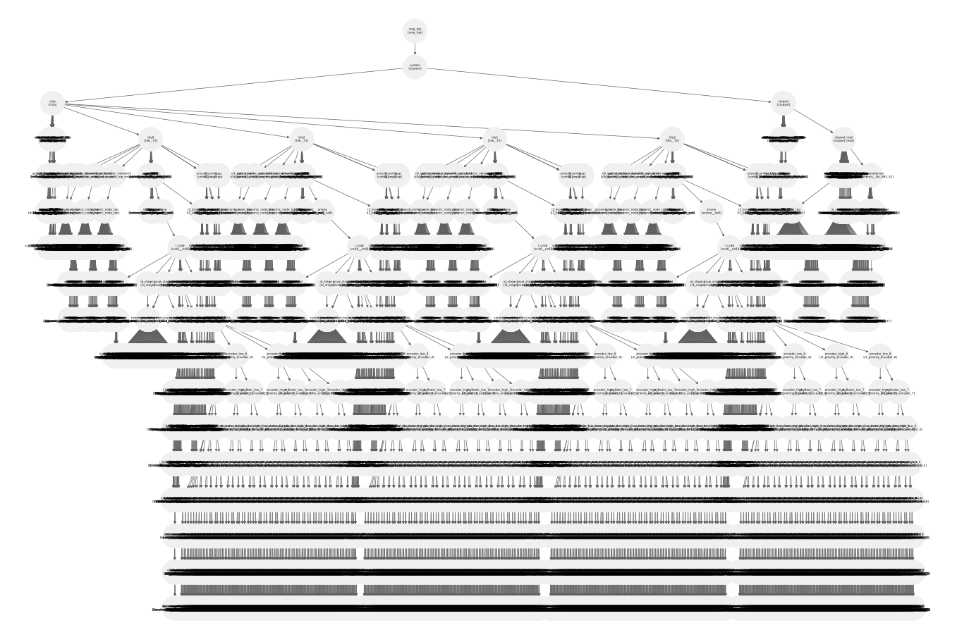
- Hierarchical Graph Construction: The visitor traverses the entire design Abstract Syntax Tree (AST), starting from the top-level module. It constructs a directed graph representing the module instantiation hierarchy. Each node in this graph corresponds to a module instance, and edges represent the parent-child relationship between instances. Key metadata is stored for each node, including its instance name, module name, and full hierarchical path. This graph acts as the foundation of further analysis, and everything else depends on it.
-
Structural Hashing: To identify structurally identical sub-hierarchies, a unique hash is generated for each node. This hash is not based on the instance name (e.g.,
$root.core_0) but on the hierarchical path of module types (e.g.,$root.Top.Core). The system uses the blake2b algorithm for this purpose. This ensures that two instances, core_0 and core_1, both of type Core under a Top module, will produce the same hash, even though their instance paths are different.To compute these hashes, we first perform a DFS traversal. Once we reach a leaf node in the AST, we calculate the hash of its module name (not instance name). We repeat this for all nodes at the same level, generating a 128-bit hash for each name since
blake2btakes variable-size input and produces a hash of fixed length. Then, as DFS moves to the parent node, we compute the hash of the parent module by operating the hash function on<parent_module>.<child0_hash>.<child1_hash>.....<last_child_hash>, again yielding a fixed-length hash.So, by choosing
blake2bwe get a consistent hash for all nodes. In this way, we are ensuring that if any two nodes have the same hash, then with certainty we can assume that the hierarchy below those nodes are exactly the same or, they represent a duplicate hardware block.
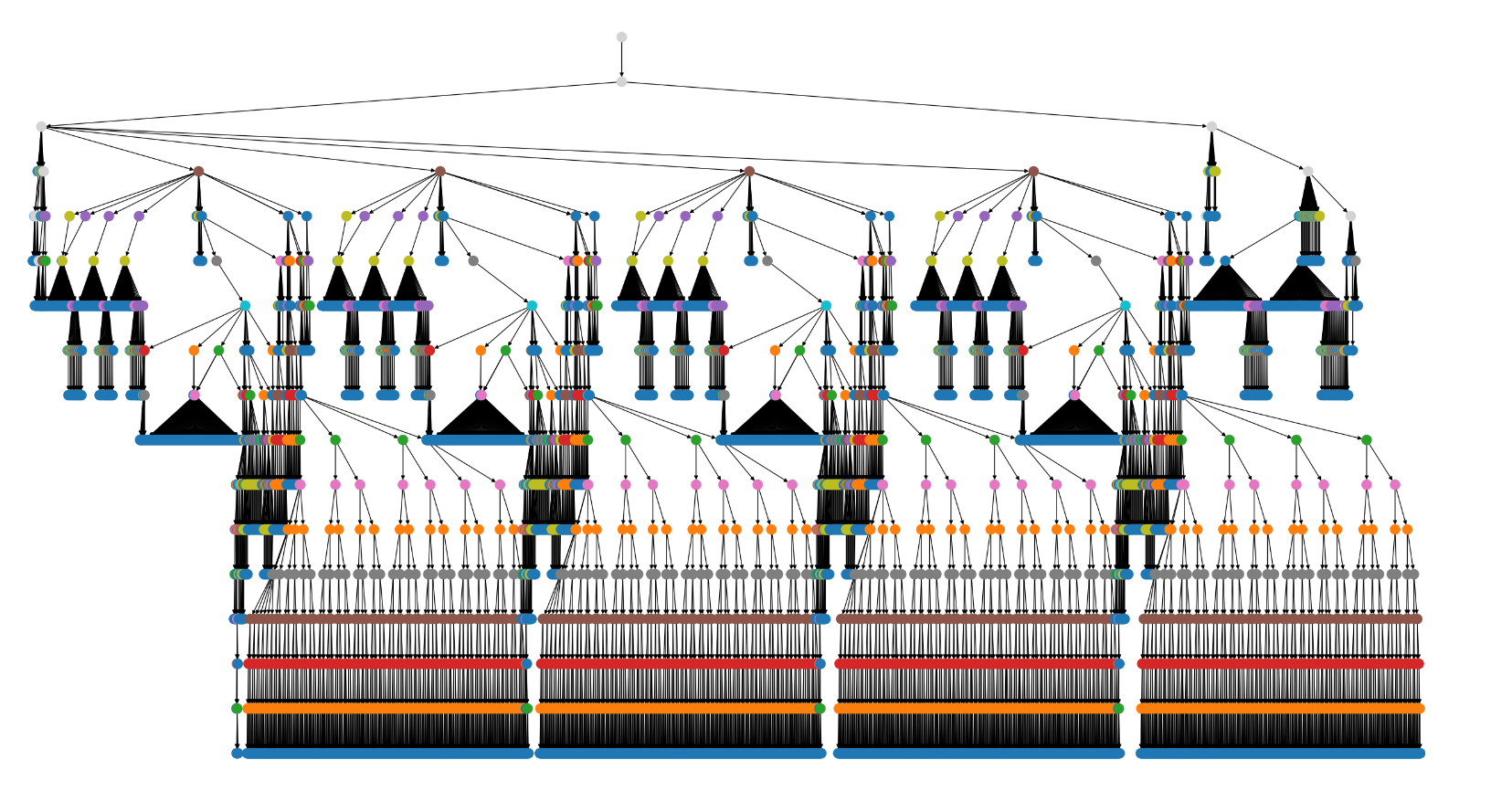
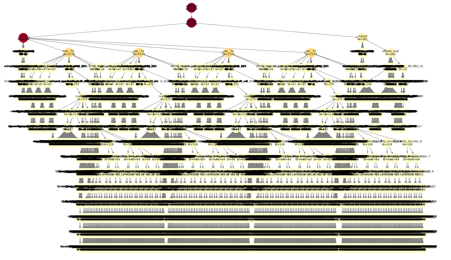
- Complexity Weighting or the Weight Model: After assigning the hashes, it became easy to find duplicate hierarchies, but this didn’t provide us any information about their size. Next, we used a weight model that assigns weights to nodes, allowing us to estimate the size of the underlying hierarchy. The current weight model is simple and works for any hardware design that has repeated hardware blocks organized as in the case of a manycore CPU. We have not tested the myriad of possible different topologies that exist in other designs, which may require changing the weight model or updating it to make it more general. This remains a future work.
-
Partition Selection (BFS): With the graph built with weights, a Breadth-First Search (BFS) is used to traverse the hierarchy level by level. At each level, the algorithm groups instances by their structural hash.
- If a hash appears more than once at a given level, it signifies the discovery of multiple, structurally identical instances that are candidates for partitioning.
- To select the best candidate set, the algorithm chooses the group of instances with the highest cumulative weight. This heuristic prioritizes partitioning the most complex or significant repeating structures in the design.
Once this “best” group is identified, the algorithm designates their common module type as the partition module and outputs the list of instance names to be analyzed further.

Detailed Connectivity Analysis
The creation of a functional MPI communication fabric is critically dependent on a detailed understanding of the design’s data flow. Before MPI structures can be generated to pass information between processes, the system must know precisely which port on a given instance connects to which peers. Therefore, after identifying the partition instances, the PartitionPortAnalyzer class is invoked to perform an exhaustive analysis of the parent module’s netlist. This step extracts the port-to-peer connectivity data required to construct the MPI layer that bridges the parallel processes.
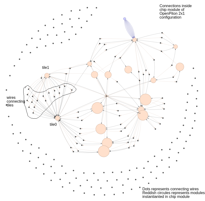
In this analysis, we also perform an optimization to reduce data movement between MPI ranks during runtime. For example, it is clear from the above image that both tiles are connected via wires defined in the chip module. Inherently, the data should flow from tile0 → chip → tile1, as wires are part of the chip module, and vice versa. However, we don’t need the messages to pass through the chip module if the two instances are directly communicating with each other.
To avoid this, the analysis recursively looks into the connections of each port of each module instance and classifies:
- which ports expect data from which other ports,
- which are for initialization (just one-time data movement), and
- which are of type “logic” (i.e., the port is driven by some logic inside the parent module — here, the chip module).
More details of this analysis are mentioned below:
- It traces signals through chained
assignstatements using theresolveWireChainfunction to find the ultimate source wire for any given port connection. - It applies a sophisticated filtering logic that intelligently prioritizes true
Outputports as data originators over passive, passthroughassignstatements, resulting in a cleaner data-flow graph. - The analyzer is capable of determining the direction of ports on any module instance within the parent scope, whether it is a designated partition or not, by maintaining a map of instance names to their AST definitions (
m_instanceToModulePtr).
Global Uniqueness and Reporting
To ensure a functional and optimized parallel simulation, the framework must guarantee that every communicating process has a unique identifier and that the results of the connectivity analysis are captured in a clear, comprehensive, and usable format.
Global Uniqueness: Deterministic MPI Rank Assignment
A fundamental requirement for any MPI-based application is that each parallel process must have a unique integer identifier, known as its rank. The PartitionPortAnalyzer class establishes a globally unique and consistent ranking system before the main analysis begins.
The assignment process is as follows:
-
System Rank: A special conceptual process named “system” is always assigned rank 0. This rank represents all non-partitioned logic, the top-level testbench, and any I/O external to the partitioned instances.
-
Deterministic Sorting: To ensure that the analysis is repeatable and stable, the list of discovered partition instance names is sorted alphabetically. This critical step prevents rank assignments from changing between different runs of the tool, which is essential for consistent builds.
-
Sequential Assignment: After sorting, the framework iterates through the list of partition instances and assigns them sequential, incremental ranks starting from 1 (e.g., 1, 2, 3, …).
-
Centralized Mapping: These assignments are stored in a map (
m_mpiRankMap), which serves as the directory for retrieving the rank for any partition instance or the system process during the analysis. The final rank for each port and its communication partners is stored directly within the Port and CommunicationPartner data structures.
The reason we introduce MPI ranks here, even though ranks are a runtime assignment/property, is because by doing this we can correlate any identifier of the partitions with the rank as we control the rank assignment. More importantly, it makes the generation of MPI structures and MPI send & receive functions very straightforward.
Reporting for Analysis and Automation
The framework generates two distinct reports from the analysis data, one tailored for human review and the other for machine consumption by downstream automation tools.
- Human-Readable Console Report (
printReport)- This function prints a formatted table directly to the console for immediate user feedback and debugging.
- The report is organized by partition instance and lists every port.
- Key columns include the port’s name, direction, width, its own assigned MPI rank and process name, and the classified communication type (
P2P,broadcast, orNULL). - Crucially, it provides formatted lists of remote partners, showing the specific instances, ports, MPI processes, and MPI ranks it communicates with, making the connectivity explicit and easy to verify.
Instance: tile0
-------------------------------------------
Port Name Direction Width Own Rank Own MPI Process Comm Type Remote Instance Remote Port Remote MPI Process Remote MPI Rank
clk in 1 1 tile0 P2P [clock_mux] [clk_muxed] [system] [0]
rst_n in 1 1 tile0 P2P [rst_sync] [syncdata] [system] [0]
clk_en in 1 1 tile0 NULL [] [] [] []
default_chipid in 14 1 tile0 NULL [] [] [] []
default_coreid_x in 8 1 tile0 NULL [] [] [] []
default_coreid_y in 8 1 tile0 NULL [] [] [] []
default_total_num_tiles in 32 1 tile0 NULL [] [] [] []
flat_tileid in 8 1 tile0 NULL [] [] [] []
debug_req_i in 1 1 tile0 NULL [] [] [] []
unavailable_o out 1 1 tile0 P2P [chip] [logic_unavailable_o] [system] [0]
timer_irq_i in 1 1 tile0 NULL [] [] [] []
ipi_i in 1 1 tile0 NULL [] [] [] []
irq_i in 2 1 tile0 NULL [] [] [] []
tile_jtag_ucb_val out 1 1 tile0 NULL [] [] [] []
tile_jtag_ucb_data out 4 1 tile0 NULL [] [] [] []
jtag_tiles_ucb_val in 1 1 tile0 P2P [jtag_port] [jtag_tiles_ucb_val] [system] [0]
jtag_tiles_ucb_data in 4 1 tile0 P2P [jtag_port] [jtag_tiles_ucb_data] [system] [0]
dyn0_dataIn_N in 64 1 tile0 NULL [] [] [] []
dyn0_dataIn_E in 64 1 tile0 P2P [tile1] [dyn0_dWo] [tile1] [2]
dyn0_dataIn_W in 64 1 tile0 P2P [chip_from_intf_noc1_v2c] [data_out_dyn0_dataIn_W] [system] [0]
dyn0_dataIn_S in 64 1 tile0 P2P [tile2] [dyn0_dNo] [tile2] [3]
dyn0_validIn_N in 1 1 tile0 NULL [] [] [] []
dyn0_validIn_E in 1 1 tile0 P2P [tile1] [dyn0_dWo_valid] [tile1] [2]
dyn0_validIn_W in 1 1 tile0 P2P [chip_from_intf_noc1_v2c] [valid_out_dyn0_validIn_W] [system] [0]
dyn0_validIn_S in 1 1 tile0 P2P [tile2] [dyn0_dNo_valid] [tile2] [3]
dyn0_dNo_yummy in 1 1 tile0 NULL [] [] [] []
dyn0_dEo_yummy in 1 1 tile0 P2P [tile1] [dyn0_yummyOut_W] [tile1] [2]
dyn0_dWo_yummy in 1 1 tile0 P2P [chip_to_intf_noc1_c2v] [yummy_in_dyn0_dWo_yummy] [system] [0]
dyn0_dSo_yummy in 1 1 tile0 P2P [tile2] [dyn0_yummyOut_N] [tile2] [3]
dyn0_dNo out 64 1 tile0 NULL [] [] [] []
dyn0_dEo out 64 1 tile0 P2P [tile1] [dyn0_dataIn_W] [tile1] [2]
dyn0_dWo out 64 1 tile0 P2P [chip] [logic_dyn0_dWo] [system] [0]
dyn0_dSo out 64 1 tile0 P2P [tile2] [dyn0_dataIn_N] [tile2] [3]
dyn0_dNo_valid out 1 1 tile0 NULL [] [] [] []
dyn0_dEo_valid out 1 1 tile0 P2P [tile1] [dyn0_validIn_W] [tile1] [2]
dyn0_dWo_valid out 1 1 tile0 P2P [chip] [logic_dyn0_dWo_valid] [system] [0]
dyn0_dSo_valid out 1 1 tile0 P2P [tile2] [dyn0_validIn_N] [tile2] [3]
dyn0_yummyOut_N out 1 1 tile0 NULL [] [] [] []
dyn0_yummyOut_E out 1 1 tile0 P2P [tile1] [dyn0_dWo_yummy] [tile1] [2]
dyn0_yummyOut_W out 1 1 tile0 P2P [chip] [logic_dyn0_yummyOut_W] [system] [0]
dyn0_yummyOut_S out 1 1 tile0 P2P [tile2] [dyn0_dNo_yummy] [tile2] [3]
dyn1_dataIn_N in 64 1 tile0 NULL [] [] [] []
dyn1_dataIn_E in 64 1 tile0 P2P [tile1] [dyn1_dWo] [tile1] [2]
dyn1_dataIn_W in 64 1 tile0 P2P [chip_from_intf_noc2_v2c] [data_out_dyn1_dataIn_W] [system] [0]
dyn1_dataIn_S in 64 1 tile0 P2P [tile2] [dyn1_dNo] [tile2] [3]
dyn1_validIn_N in 1 1 tile0 NULL [] [] [] []
dyn1_validIn_E in 1 1 tile0 P2P [tile1] [dyn1_dWo_valid] [tile1] [2]
dyn1_validIn_W in 1 1 tile0 P2P [chip_from_intf_noc2_v2c] [valid_out_dyn1_validIn_W] [system] [0]
dyn1_validIn_S in 1 1 tile0 P2P [tile2] [dyn1_dNo_valid] [tile2] [3]
dyn1_dNo_yummy in 1 1 tile0 NULL [] [] [] []
dyn1_dEo_yummy in 1 1 tile0 P2P [tile1] [dyn1_yummyOut_W] [tile1] [2]
dyn1_dWo_yummy in 1 1 tile0 NULL [] [] [] []
dyn1_dSo_yummy in 1 1 tile0 P2P [tile2] [dyn1_yummyOut_N] [tile2] [3]
dyn1_dNo out 64 1 tile0 NULL [] [] [] []
dyn1_dEo out 64 1 tile0 P2P [tile1] [dyn1_dataIn_W] [tile1] [2]
dyn1_dWo out 64 1 tile0 P2P [chip] [logic_dyn1_dWo] [system] [0]
dyn1_dSo out 64 1 tile0 P2P [tile2] [dyn1_dataIn_N] [tile2] [3]
dyn1_dNo_valid out 1 1 tile0 NULL [] [] [] []
dyn1_dEo_valid out 1 1 tile0 P2P [tile1] [dyn1_validIn_W] [tile1] [2]
dyn1_dWo_valid out 1 1 tile0 P2P [chip] [logic_dyn1_dWo_valid] [system] [0]
dyn1_dSo_valid out 1 1 tile0 P2P [tile2] [dyn1_validIn_N] [tile2] [3]
dyn1_yummyOut_N out 1 1 tile0 NULL [] [] [] []
dyn1_yummyOut_E out 1 1 tile0 P2P [tile1] [dyn1_dWo_yummy] [tile1] [2]
dyn1_yummyOut_W out 1 1 tile0 P2P [chip] [logic_dyn1_yummyOut_W] [system] [0]
dyn1_yummyOut_S out 1 1 tile0 P2P [tile2] [dyn1_dNo_yummy] [tile2] [3]
dyn2_dataIn_N in 64 1 tile0 NULL [] [] [] []
dyn2_dataIn_E in 64 1 tile0 P2P [tile1] [dyn2_dWo] [tile1] [2]
dyn2_dataIn_W in 64 1 tile0 NULL [] [] [] []
dyn2_dataIn_S in 64 1 tile0 P2P [tile2] [dyn2_dNo] [tile2] [3]
dyn2_validIn_N in 1 1 tile0 NULL [] [] [] []
dyn2_validIn_E in 1 1 tile0 P2P [tile1] [dyn2_dWo_valid] [tile1] [2]
dyn2_validIn_W in 1 1 tile0 NULL [] [] [] []
dyn2_validIn_S in 1 1 tile0 P2P [tile2] [dyn2_dNo_valid] [tile2] [3]
dyn2_dNo_yummy in 1 1 tile0 NULL [] [] [] []
dyn2_dEo_yummy in 1 1 tile0 P2P [tile1] [dyn2_yummyOut_W] [tile1] [2]
dyn2_dWo_yummy in 1 1 tile0 P2P [chip_to_intf_noc3_c2v] [yummy_in_dyn2_dWo_yummy] [system] [0]
dyn2_dSo_yummy in 1 1 tile0 P2P [tile2] [dyn2_yummyOut_N] [tile2] [3]
dyn2_dNo out 64 1 tile0 NULL [] [] [] []
dyn2_dEo out 64 1 tile0 P2P [tile1] [dyn2_dataIn_W] [tile1] [2]
dyn2_dWo out 64 1 tile0 P2P [chip] [logic_dyn2_dWo] [system] [0]
dyn2_dSo out 64 1 tile0 P2P [tile2] [dyn2_dataIn_N] [tile2] [3]
dyn2_dNo_valid out 1 1 tile0 NULL [] [] [] []
dyn2_dEo_valid out 1 1 tile0 P2P [tile1] [dyn2_validIn_W] [tile1] [2]
dyn2_dWo_valid out 1 1 tile0 P2P [chip] [logic_dyn2_dWo_valid] [system] [0]
dyn2_dSo_valid out 1 1 tile0 P2P [tile2] [dyn2_validIn_N] [tile2] [3]
dyn2_yummyOut_N out 1 1 tile0 NULL [] [] [] []
dyn2_yummyOut_E out 1 1 tile0 P2P [tile1] [dyn2_dWo_yummy] [tile1] [2]
dyn2_yummyOut_W out 1 1 tile0 P2P [chip] [logic_dyn2_yummyOut_W] [system] [0]
dyn2_yummyOut_S out 1 1 tile0 P2P [tile2] [dyn2_dNo_yummy] [tile2] [3]
-
Machine-Readable JSON Report (
writeJsonReport)- This function is the primary output for the entire analysis pipeline, serializing the results into a structured JSON file named
metro_mpi/partition_report.json. - This file serves as a standardized data interchange format for subsequent code generation steps, such as creating MPI wrappers, C++ drivers, and Makefiles.
- The JSON structure is hierarchical, with a top-level
partitionsobject containing entries for each analyzed instance. Each instance contains a detailed array of its ports. -
Each port object in the JSON is comprehensive, containing fields for:
- Basic properties:
port_name,direction,width. - Connection details:
active,type,connecting_wire. - MPI Identity: Its own
mpi_processandmpi_rank. - Communication Profile: The
Commfield, indicating the communication type (P2P,broadcast, etc.). - Partner List: A
with_whom_is_it_communicatingarray, which contains a list of objects, each detailing a remote partner’sinstance,port,mpi_process, andmpi_rank.
- Basic properties:
{ "partitions": { "tile0": [ { "port_name": "clk", "direction": "in", "width": 1, "active": "Yes", "type": "wire", "connecting_wire": "clk_muxed", "mpi_process": "tile0", "mpi_rank": 1, "Comm": "P2P", "with_whom_is_it_communicating": [ { "instance": "clock_mux", "port": "clk_muxed", "mpi_process": "system", "mpi_rank": 0 } ] }, .... { "port_name": "dyn0_dEo", "direction": "out", "width": 64, "active": "Yes", "type": "wire", "connecting_wire": "tile_0_0_out_E_noc1_data", "mpi_process": "tile0", "mpi_rank": 1, "Comm": "P2P", "with_whom_is_it_communicating": [ { "instance": "tile1", "port": "dyn0_dataIn_W", "mpi_process": "tile1", "mpi_rank": 2 } ] }, .... ], "tile1": [.....] } } - This function is the primary output for the entire analysis pipeline, serializing the results into a structured JSON file named
Verilog Rewriting for MPI Integration
After the connectivity analysis is complete and the partition_report.json is generated, the Metro-MPI framework transitions from analysis to code generation. The MPIFileGenerator class, as referenced in HierCellsGraphVisitor::findAndPrintPartitionPorts, orchestrates a multi-step process to modify the original Verilog source code. This rewriting is essential to intercept communication to and from the partitioned modules and redirect it through the MPI-enabled C++ simulation environment. The process involves creating new Verilog modules and modifying existing ones to integrate the necessary simulation hooks.
1. DPI Stub Generation
The bridge between the Verilog simulation domain and the C++ MPI domain is the SystemVerilog Direct Programming Interface (DPI). The framework automatically generates a C++ header file (metro_mpi_dpi.h) containing DPI “import” function declarations. These functions act as stubs that the Verilog code can call.
The generation process, managed within the MPIFileGenerator’s logic, proceeds as follows:
- Iterating Through Partitions: The generator reads the
partition_report.jsonfile, iterating through each partitioned instance and its list of ports. - Identifying Active Ports: It specifically looks for ports marked as
"active": "Yes". Only ports that are actually connected to other parts of the design require MPI communication channels. - Directional Function Generation: For each active port, two distinct DPI functions are generated based on its direction:
- For Output Ports: A
metro_mpi_send_<instance_name>_<port_name>function is declared. This function will be called from Verilog whenever the partitioned module drives a new value on its output. The function signature is designed to accept an argument of a type corresponding to the port’s width (e.g.,intfor a 32-bit port), which will be the value to send over MPI. - For Input Ports: A
metro_mpi_recv_<instance_name>_<port_name>function is declared. This function will be called by the Verilog wrapper to receive an updated value for an input port from the MPI network. It is declared with a return type corresponding to the port’s width.
- For Output Ports: A
- Unique Naming Convention: The naming convention (
metro_mpi_send/recv_<instance_name>_<port_name>) is critical. It ensures that each generated DPI stub is globally unique, preventing naming collisions even if multiple instances have ports with the same name (e.g.,clkorrst). This allows the C++ backend to link each Verilog-side call to a specific instance and port in the simulation.
The resulting metro_mpi_dpi.h file contains a list of C-style function prototypes that will be implemented in a separate C++ file (metro_mpi.cpp, generated by MPICodeGenerator). This header is included by the Verilog simulator, making these C++ functions visible and callable from the hardware design.
2. Instance-Specific Wrappers
The original partitioned module (<PartitionModuleName>.v) is not modified. Instead, for each instance identified for partitioning (e.g., core_0, core_1), the framework generates a new, instance-specific Verilog wrapper module. For an instance core_0 of module Core, a new file named metro_mpi_wrapper_core_0.v is created.
This wrapper module serves as a crucial intermediary:
- Module Instantiation: The wrapper contains a single instantiation of the original partitioned module (e.g.,
Core u_core (...)). - I/O Mirroring: The wrapper module’s port list is identical to that of the original module it is wrapping. This makes it a “drop-in” replacement in the parent module.
- Connecting to DPI Stubs: The core logic of the wrapper involves redirecting the I/O of the instantiated module to the DPI function calls.
- Inputs: For each input port (e.g.,
data_in), the wrapper does not connect it to an external wire. Instead, it continuously calls the corresponding DPI receive function:assign data_in = metro_mpi_recv_core_0_data_in();. This ensures the instantiated module receives its inputs from the MPI network. - Outputs: For each output port (e.g.,
data_out), the wrapper connects the port to an internal wire. It then uses analways @(*)block to monitor this wire for any changes. When a change is detected, it calls the corresponding DPI send function:always @(*) metro_mpi_send_core_0_data_out(data_out);. This logic effectively captures every value change on an output port and sends it to the C++ simulation environment via the DPI stub.
- Inputs: For each input port (e.g.,
This strategy cleverly isolates the original design logic. The core module remains untouched, while the wrapper provides the necessary “hooks” to interface with the external MPI simulation driver.
3. Parent Module Modification
The final step in the Verilog rewriting process is to modify the parent module—the module that originally contained the partitioned instances. This is the most invasive step, but it is performed programmatically to ensure correctness.
The MPIFileGenerator performs the following actions:
- Reading the Original Source: The generator reads the source file of the parent module into memory.
- Locating and Replacing Instantiations: It parses the Verilog text to find the lines of code corresponding to the instantiation of the partitioned modules (e.g.,
Core core_0 (...),Core core_1 (...)). - Substitution with Wrappers: Each original instantiation is commented out or removed and replaced with an instantiation of its corresponding, newly generated wrapper module.
-
Core core_0 (...)becomesmetro_mpi_wrapper_core_0 core_0 (...). - The port connections (
.port(wire)) in the instantiation remain identical, as the wrapper was designed to have a matching I/O signature.
-
- Writing the Modified File: The modified source code is written back to a new file, typically with a
_metro_mpi.vsuffix, to preserve the original file. This new file is then used in the MPI simulation’s compilation list.
By replacing the original instances with their MPI-enabled wrappers, the framework effectively severs the direct wire-level connections between the partitions and the rest of the design. All communication is now forced to flow through the DPI interface, into the C++ domain where it can be managed by the MPI runtime, and back into the Verilog simulation, enabling true parallel execution of the partitioned hardware blocks.
C++ Simulation and Harness Code Generation
After the Verilog sources have been rewritten, the Metro-MPI framework proceeds to generate all the necessary C++ source code to build the final, distributed simulation executables. The generation process is orchestrated by the HierCellsGraphVisitor class, which calls a series of specialized generator classes that use the partition_report.json as their primary input.
1. MPI Communication Layer
The core of the communication system is a C++ layer that implements the DPI functions declared in metro_mpi_dpi.h. This layer translates the function calls made from the Verilog domain into actual MPI network operations.
The MPICodeGenerator class is responsible for creating this file. It reads the JSON report to understand the complete communication graph—which port on which instance communicates with whom. For each send and receive DPI stub, it generates a corresponding C++ function body that:
- Uses the unique function name (e.g.,
metro_mpi_send_core_0_data_out) to identify the source instance and port of the communication. - Consults the connectivity data from the JSON report to determine the destination MPI rank(s) for a
sendoperation or the source rank for areceiveoperation. - Implements the function using the appropriate MPI library calls (e.g.,
MPI_Send,MPI_Recv). - Handles the communication type correctly, issuing a point-to-point
MPI_Sendfor a port with a"Comm": "P2P"profile, or potentially a series of sends or a collective operation likeMPI_Bcastfor a"Comm": "broadcast"profile.
This generated C++ file effectively serves as the middleware that bridges the Verilated hardware model with the MPI runtime system.
2. Partition Simulation Executable
Each partitioned module must be compiled into its own standalone executable that will run on MPI ranks greater than zero (1, 2, 3, etc.). The MPIMainGenerator class is responsible for generating the main C++ driver file for these executables.
The generate method of this class takes the original partition module name as an argument (e.g., Core). It creates a C++ source file containing a main() function that performs the following steps:
- Initializes the MPI environment.
- Gets its own MPI rank to identify which instance it represents.
- Instantiates the Verilated C++ model of the partitioned module (e.g.,
VCore* top = new VCore;). - Enters a simulation loop that runs as long as the simulation has not finished (
while (!Verilated::gotFinish())). - Inside the loop, it repeatedly calls the model’s evaluation function (
top->eval()). - Execution within this loop is implicitly managed by the MPI communication layer. When the
eval()function triggers a call to ametro_mpi_recv_*DPI function, the executable will block until the required data is received from another MPI process, thus ensuring synchronization across the distributed simulation.
3. Rank 0 Testbench Harness
The entire distributed simulation is controlled by a master process running on Rank 0. This process runs the top-level testbench, drives primary inputs like clock and reset, and manages the overall simulation time. The Rank0MainGenerator class is responsible for generating this master testbench harness.
The code first carefully determines the correct top-level module name for the Rank 0 simulation, even accounting for Verilator’s process of wrapping the user’s design in a $root module. The generate function is then called with this top module name. The resulting C++ file contains a main() function that:
- Initializes the MPI environment.
- Instantiates the Verilated C++ model of the top-level design (e.g.,
VTestbench* top = new VTestbench;). - Initializes and manages a global simulation time variable.
- Drives the simulation by toggling the clock, managing reset signals, and calling the top-level model’s
eval()function within a time-based loop. - When the simulation is complete (e.g.,
$finishis called in Verilog), it orchestrates a clean shutdown of all MPI processes.
Build System Generation
A key feature of the Metro-MPI framework is its ability to automatically generate a complete build system for the complex, multi-executable MPI simulation. This process, orchestrated within the HierCellsGraphVisitor class, ensures that all components (Verilog wrappers, C++ harnesses, and communication layers) are compiled and linked correctly with the necessary MPI libraries and user-defined configurations.
1. Makefile Generation
The framework automates the creation of a Makefile by using a dedicated MakefileGenerator class. This component is responsible for producing a build script tailored to the specific partitioning results.
The generation process is informed by a detailed analysis of the design’s source file dependencies. A recursive function, collectPartitionFiles, traverses the design hierarchy of the partitioned module to gather a unique set of all .v or .sv source files it depends on. This list of files, along with the name of the top-level partition module, is passed to the makefileGenerator.generate method. This allows the generator to create specific build rules in the Makefile for compiling the partition module into its own object files, separate from the rules for compiling the main Rank 0 testbench harness.
2. Configuration Preservation
To ensure a consistent and correct build, it is critical that any command-line options passed to the initial Verilator run (such as include directories, defines, optimization flags, or tracing options) are preserved in the final MPI build.
The framework achieves this through an extern std::string argString variable. This variable captures the original command-line arguments. The argString is then passed directly to the MakefileGenerator’s generate method. The generator incorporates these preserved arguments into the compilation commands within the Makefile, ensuring that the Verilation of both the partition and top-level modules occurs with the exact same configuration intended by the user.
3. MPI Compiler Integration
Compiling and linking C++ applications with an MPI library requires using a special compiler wrapper, such as mpic++. This wrapper automatically includes the necessary MPI header paths and links against the required MPI libraries.
The MakefileGenerator, being a core component of an MPI-centric tool, is designed to integrate this requirement seamlessly. It generates Makefile rules that invoke the mpic++ compiler (or an equivalent) for all C++ compilation and linking steps. By generating a Makefile that uses the appropriate MPI compiler, the framework abstracts away the complexity of locating and linking the MPI libraries, providing a simple and robust build process for the user.
Code
We can see the repo that I worked on-
verilator - here
Metro-MPI - here